Flowmeter Installations

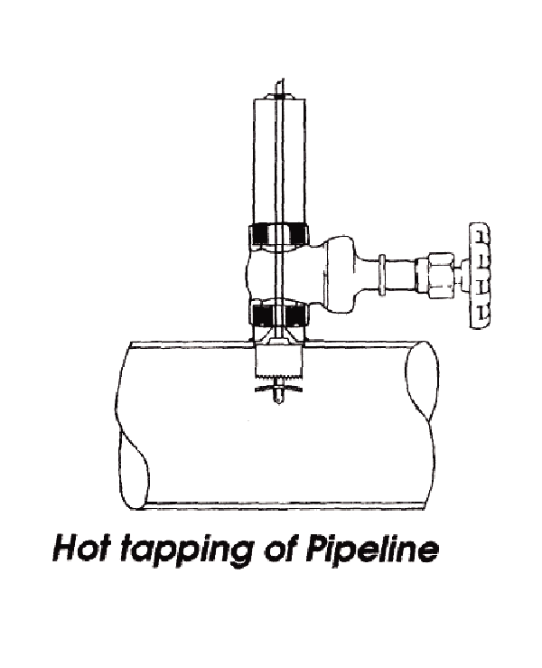
Hot Tapping Pipe for a Flowmeter Installation
The Tee-Outlet-let Fitting has been welded to the desired pipeline location and a 2" gate, or ball valve, has been installed and pressure tested. A 1-7/8" hole has been hot tapped into the system using an IFT T-1 tapping machine. The "coupon", or cut portion, has been held by a retention device on the pilot drill. The "coupon" is retracted above the valve and the valve is then closed. At this point, the tapping machine can be removed.

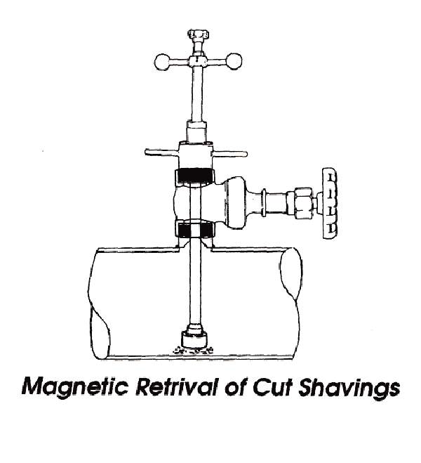
Magnetic Retrieval of Cut Shavings
After the tapping procedure is completed, a magnetic retrieval device is installed onto the valve and the valve is opened. The magnet is inserted past the valve to the bottom of the pipeline where shavings may sit. Since some flow devices utilize magnetic components to help calculate the measurement of flow, it is important to remove the shavings from the line. The magnet is then retracted above the valve, and the valve is closed so that the retrieval device may be removed and cleaned.

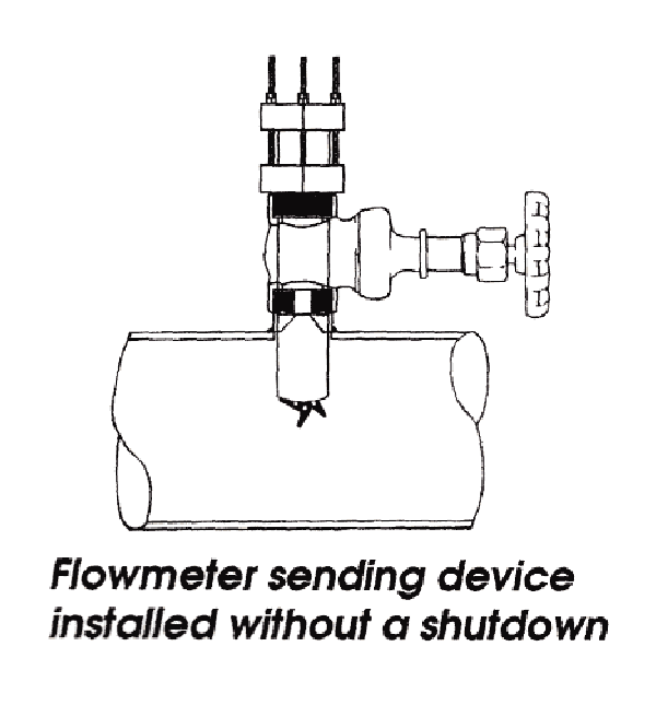
Flowmeter Device Installed without a Shutdown
Insertion of the flowmeter, into the pipeline, begins by securing the meter to the valve, and opening the valve. A seal in the metering device keeps any water flow from escaping, while the paddle wheels are pushed past the valve, to a predetermined depth, inside the pipe. The meter is then held in position by three threaded rods. Under high pressure, the force pushing against the meter is too great to insert it to the desired depth in the pipe. An inserting tool (IT- #102) must be used to install and retract the meter. Once the meter is installed, the wires can be hooked up to a number of recording instruments and monitors.
The Services Division of International Flow Technologies, Inc. has designed flowmeter installation machinery capable of installing technical sensing devices, which relay information to a monitoring station. IFT Services Division has the capability to install most flowmeter sending devices into pressurized mains, without a shutdown.
IFT can provide flowmeters and/or install your meters without interrupting service. A number of flowmeter models are available for a wide range of pipe sizes, temperatures, pressures, and purposes.
The most common type of flowmeter generates a frequency which is proportional to the flow rate. An internal pre-amplifier allows the pulse signal to travel up to 2000 feet without amplification.
Power to operate the meter is provided by the flow monitor or an external source. The impeller shaft, o-rings, and impeller bearings are replaceable in the field.
IFT uses flowmeters that feature a closed, six blade impeller design. As the liquid flow turns the impeller, a low impedance 8V DC signal is transmitted with a frequency proportional to the flow rate.
The accuracy of flow measurement for all measuring devices is highly dependent on proper installation and location in the piping system. Irregular flow velocity profiles caused by valves, fittings, pipe bends, etc. can lead to inaccurate overall flow rate indications even though local flow velocity measurements may be accurate. A meter located in the pipe where it can be affected by debris or air in the pipeline may not achieve full accuracy and could possibly be damaged. IFT meters are designed to be reliable under the most diverse conditions, but the following recommendations should be considered when installing the meter to ensure maximum efficiency and accuracy.
1) Choose a location on the pipe where a distance of 10 diameters upstream and 5 diameters downstream of the meter provide no flow disturbance. Pipe bends, valves or other fittings, and pipe enlargements and reductions should not be present in this area of the pipe.
2) The preferred location of a meter on a horizontal pipe is on top, or not more than 45 degrees from the top, dead center. The meter should never be located at the bottom of the pipe, as sediment may collect and disrupt accuracy or damage the meter. Locations off of top dead center will cause impeller friction to increase, which may affect the meter's performance at low flow rates. Any location is correct for installations on vertical pipelines.
3) An insertion depth of 1-1/2" for pipe sizes of 2.5" and larger is required for various meter mounting configurations to ensure accuracy.
4) Alignment of the meter’s impeller rotation parallel to flow is important.

